

Technology Venturing Forward
Blueprint 3D

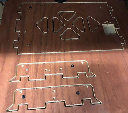
The Y-axis was designed to have a dual purpose. to ensure that the print bed is rigidly attached and to reinforce the printer frame when slid in place. These parts were prototyped first to ensure that the design was manufacturable and fulfilled the intent. Furthermore, it allowed me to see what tolerances the hobbyist CNC mill could hold.


The X-axis was then assembled using more 3D printed parts and standard hardware. The TitanAero extruder was chosen due to its compact footprint and high quality specs. This compactness made it challenging to design a sufficiently rigid carriage and have enough room for an inductive probe. After those components were made, the rest of the frame was milled on the CNC and put together.
The final prototype can bee seen below. The unfolded configuration has a calibration cube on it. The other picture is the printer in it is folded up. The programming of the printer was done using the marlin software. Many custom features were added to the code, such as the printer going into folding configuration after each print.

I had the idea for this briefcase 3D printer my senior year of high school. The original thought was to make 3D printing easily transportable for robotic competitions and for other classes to be able to use. I revisited this idea my second year of college and pursued it as an independent study. The goals of the project were to make a printer capable of printing a full volume 200mm cube, while being able to fly as a carry on. The first part of the project was designing the frame in Solidworks to find he best configuration. It was intended to make the design cheap, and the parts easily obtainable or manufacturable. The main frame components are made of plywood and 3D printed joints.

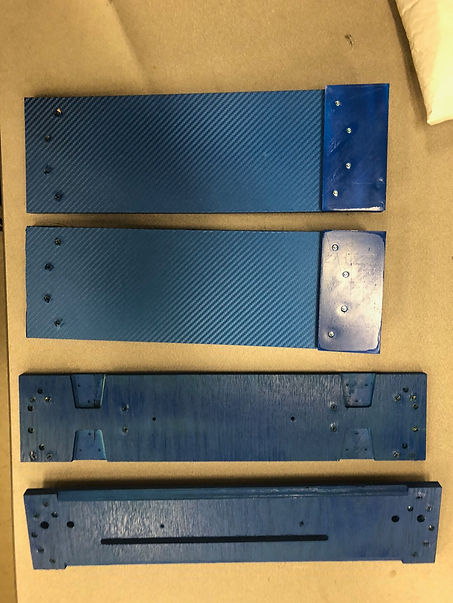
The final Y-axis prototype was manufactured once the previous design flaws had been fixed. An aluminum bed carriage had been made using a laser cutter and sheet aluminum. The blue parts were 3D printed on my heavily modified Prusa-i3 clone. The largest challenge in make this assembly was manufacturing the wooden pieces on a table CNC. It took a while to find the right setting to keep the needed tolerances.


The pockets that were milled out for the hinges proved to be the largest bottle neck of the project. The CNC had to mill very slowly to obtain the required depth. A room for improvement would be to make the hinge pockets larger to allow for easier manufacturing and assembly. A blue vinyl was placed over the outside of the wood to protect from moisture/water exposure and give the design a more finished look.

